Shane AO REDWOODS Setup
Shortcuts: ShaneAO/real to REDWOODS/tooreal | REDWOODS/tooreal to ShaneAO/real
ShaneAO/real to REDWOODS/tooreal Setup
It is helpful to have the ShaneAO toolbox and the MEMS DM controller card, in its antistatic envelope, handy before starting this procedure. When ShaneAO is on the telescope, the tooreal computer is mounted on the south side of the TUB, above the ShaneAO instrument. The instructions below, assume the instrument is on the telescope.
- Turn off [B3] TTCamera
- Turn off [B4] WFS camera
- Turn off [B5] Woofer DM
- Turn off [B6] Tweeter MEMS DM
- Turn off [B8] White Light Source
- Turn off [C5] Acquisition (flea) camera
- Turn off [C6] MEMS pico motors
- Turn off [C8] Phase Screen
- Shutdown the SAO software (leave everything
else running):
- Close saocon_gui
- Exit peeko
- Exit ttpeeko
- Exit shaneao
- Close real message log window
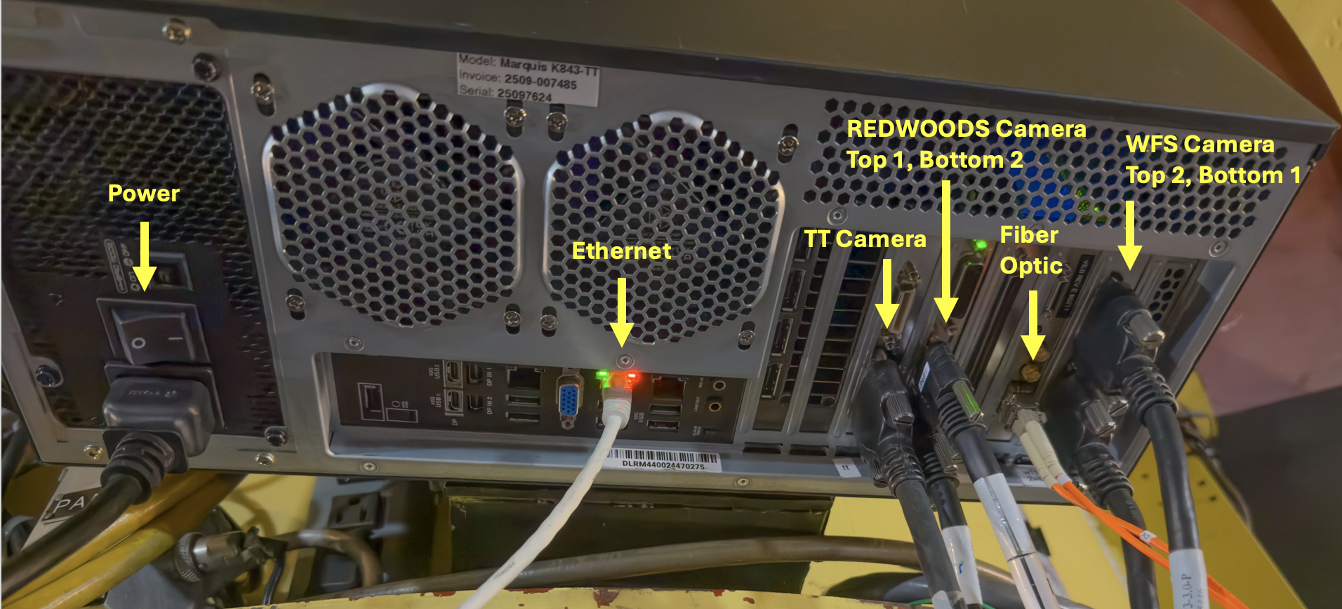
- Connect cables to tooreal (see Figure 1):
- Power cable (usually connected by TT when installing tooreal). The cable is unique, and plugs into a nearby power outlet on TUB.
- Orange fiber optic cable. Put the little white fiber optic protective caps in the small round storage bin in the top tray of the AO toolkit. Strain relieve cable to bottom of TUB rack on the east side of the telescope (Figure 2).
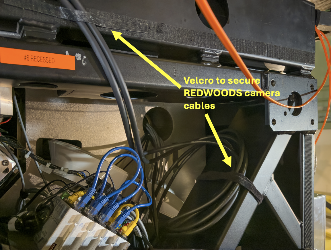
- REDWOODS camera cables. #1 goes to the top port (cable can be screwed in for stable connection). #2 goes to the bottom port (the standoffs for the cable are conneted to the screws on the cable and pulled out from the camera card, so connection cannot be firmly secured). Strain relieve cables with velcro to the ShaneAO frame (see Figure 3).
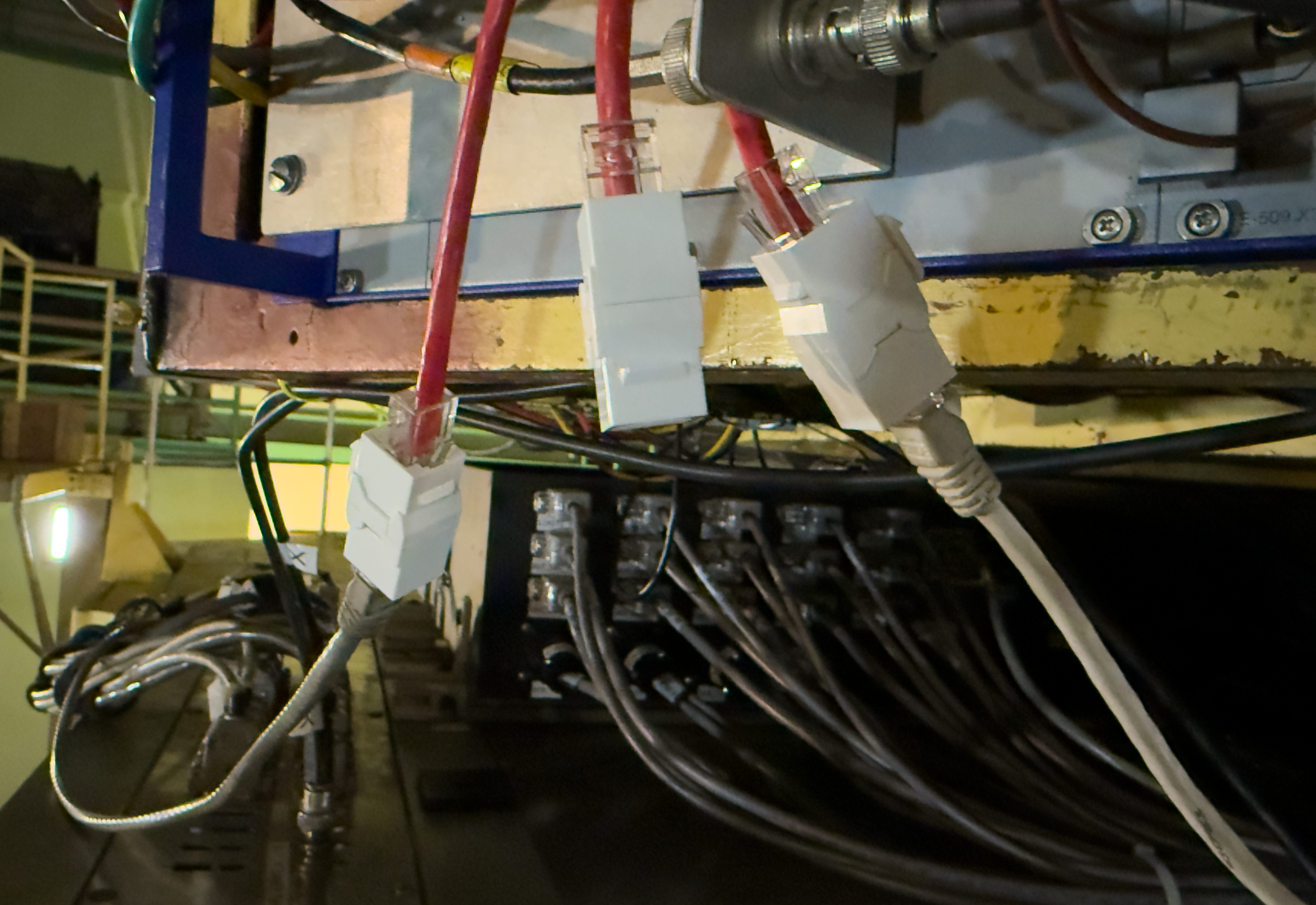
- Connect Ethernet Cable to middle ethernet port on tooreal. Connect other end to any available port on the TUB (see Figure 4).
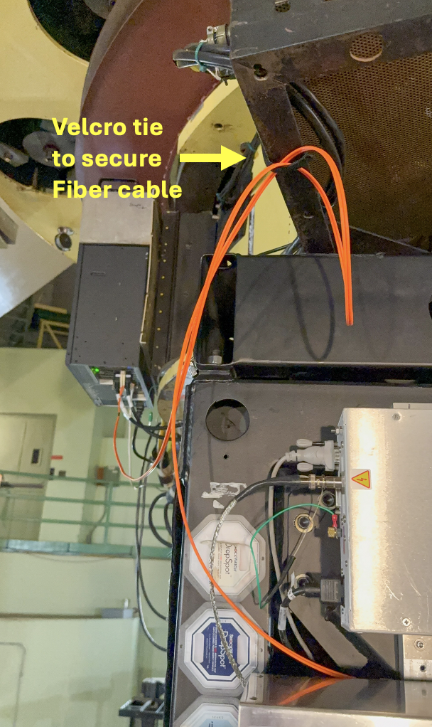
Figure 2: Orange Fiber Optic cable strain relief. - Swap MEMS DM controller Card:
- Remove DM controller protective cover by removing the four nuts and washers (be careful not to drop them) and sliding them off the bolts (see Figure 5).
- Disconnect the DM ribbon cable from the controller card (see Figure 6).
- Unscrew the two captive screws securing the controller card.
- Remove controller card by pushing in the red tabs while pushing the black card handles outwards. The card should pop out easily. If not, the screws might not have been fully unscrewed.
- Remove fiber DM controller card from antistatic envelope and place on top of envelope for easy access.
- Carefully remove the ribbon cable DM controller card and place it in the antistatic envelope.
- Install fiber DM controller card into DM controller chassis. Make sure it slides in easily and snaps into place.
- Screw in the two card screws to secure.
- Connect orange fiber optic cable, placing the two little white fiber optic covers in the small round storage container in the top tray of the AO toolkit.
- Install the DM controller protective cover with the four nuts and washers. Make sure the fiber optic cable has adequate strain relief to the bottom of the TUB rack above (see Figure 2), and that the loose ribbon cable is tucked safely inside the cover.
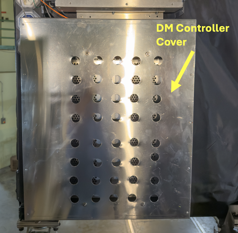
Figure 5: DM Controller Cover. 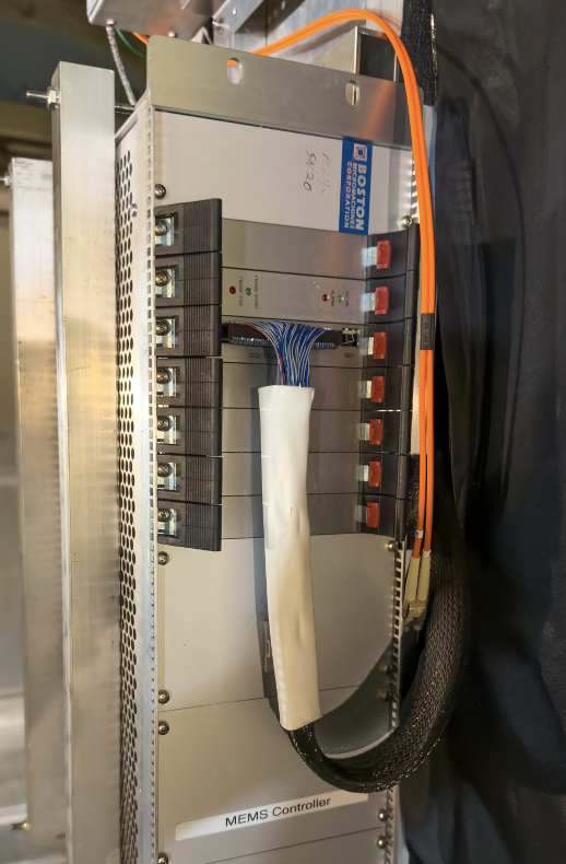
Figure 6: DM Ribbon Cable. - Disconnect TT camera and WFS Camera cables from real:
- Remove front cover of electronics rack (north side when on telescope), by loosening the butterfly screws (you may need the stubby screwdriver from the AO toolkit for the ones that have lost their butterflies) and lifting off the cover.
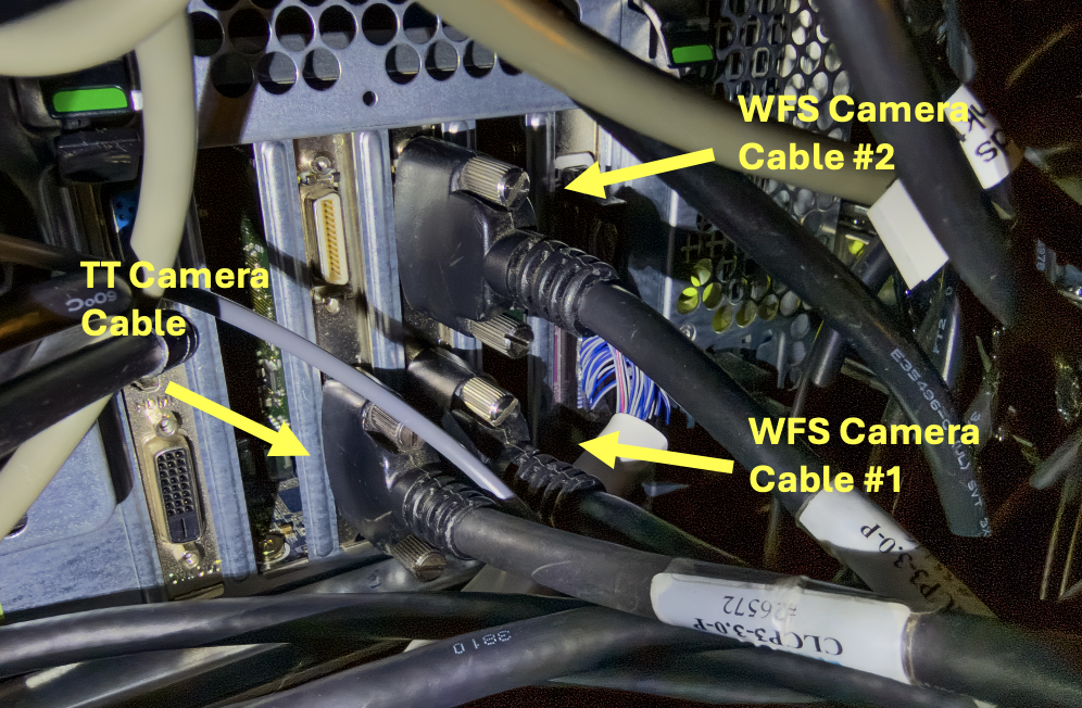
- The three cables (one for the TT Camera and two for the WFS Camera), can be unscrewed from real (see Figure 7) and uncoiled in preparation for routing to tooreal.
- Plug in REDWOODS devices in electronics rack: Outlets C5, C6, and C8 on the Pulizzi power controller are used for REDWOODS. Make sure that the appropriately labeled power cables are plugged in to the Pulizzi connectors. Note, C8 is connected to a three plug extender that has plugs labeled C8 and REDWOODS Pico Motor. the three plug extenders is what gets plugged into outlet C8 (see Figure 8).
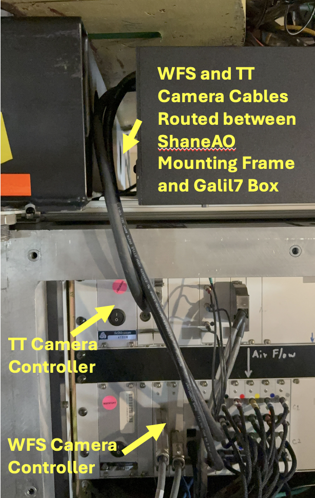
- Route TT and WFS Camera cables to tooreal:
- Neatly route cables over the AO electronics rack, between the Galil7 motor controller box and the AO mounting rack (see Figure 9).
- Install the electronics rack cover, making sure the three camera cables are flush against the top edge of the rack. The cover is flexible enough to attach all but the upper left butterfly screw.
- Strain relieve cables to the bottom of the southwest TUB rack (need to get photo of this).
- Connect TT and WFS Camera cables to tooreal (see
Figure 1):
- The TT cable has black thumbscrew handles and connects to the lefthand EDT camera controller card, bottom port. Screw in securely.
- The two WFS camera cables connect to the righthand EDT camera contoller card and are labeled 1 and 2. Cable 1 connects to the bottom port. Cable 2 connects to the top port. Securely screw in the connector screws.
- Adjust cable strain relief as needed.
- Turn on tooreal using the rocker switch. It takes 5 minutes to boot. After 5 minutes, check that tooreal responds to pings. Try to log into tooreal as rtc (contact E. Gates for password if needed).
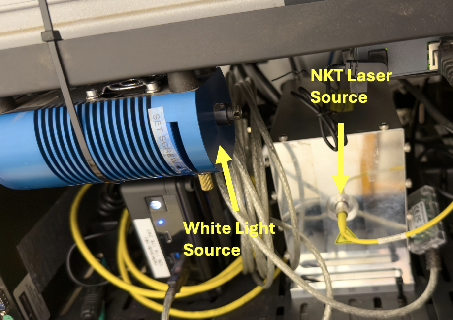
- Move light source fiber to NKT laser:
- Remove back electronics rack cover (south side if on telescope) by loosening the butterfly screws (using the stubby screwdriver if the butterflies have been lost), and lift off cover.
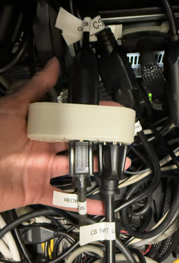
- Move yellow fiber optic cable from the white light source (blue cylindrical chassis) to the NKT fiber chuck (silver rectangular housing) (see Figure 10).
- Install back electronics rack cover.
- To configure the REDWOODS optics, refer to the REDWOODS setup document.
- Configure REDWOODS for instrument change, refer to the REDWOODS setup document. In particular, we want to be sure the flip mirror is out, so light gets to ShARCS, APALO, or APALO2.
- Turn off the following from the saopower_ui GUI:
- [B3] TT Camera
- [B4] WFS Camera
- [B5] Woofer DM
- [B6] Tweeter MEMS DM
- [B8] White Light Source
- [C5] Acquisition (flea) camera
- [C6] MEMS pico motors
- [C8] Phase Screen
- Move light source fiber to the White Light Source:
- Remove back electronics rack cover (south side if on telescope) by loosening the butterfly screws (using the stubby screwdriver if the butterflies have been lost), and lift off cover.
- Move yellow fiber optic cable from the NKT fiber chuck (silver rectangular housing) to the white light source (blue cylindrical chassis) (see Figure 10).
- Install back electronics rack cover.
- If it is the end of the AO run or if
tooreal/vm-real won't be used again during the run, shutdown tooreal
from the rtc account:
sudo /sbin/shutdown -h now
- Disconnect the TT and WFS Camera cables from tooreal (see Figure 1).
- Reroute TT and WFS Camera cables to real:
- Remove strain relief from bottom of southwest TUB rack (need photo of this).
- Route cables out from between the ShaneAO mouting rack and Galil7 box (see Figure 9).
- Remove front electronics rack cover (north side if on telescope) by loosening the buttrfly screws (using the stubby screwdriver if the butterflies have been lost), and lift off cover.
- Carefully coil each cable and install at bottom of electronics rack and connect to real (see Figure 7). I recommend the following order:
- WFS Cable #1, bottom port of righthand card.
- WFS Cable #2, top port of righthand card.
- TT Cable (black thumb screws), bottom port of lefthand card.
- Unplug C5 and C8, if need to switch to APALO or APALO2. We generaly leave C6 (the NKT computer) plugged in unless we really need the outlet for another instrument.
- Install electronics rack front cover.
- Swap MEMS DM Controller Card:
- Remove DM controller protective cover by removing the four nuts and washers (be careful not to drop or lose them) and sliding them off the bolts (see Figure 5).
- Disconnect the fiber optic cable from the controller card. Install the little white fiber end protectors (stored in the round container in the top tray of the AO toolkit).
- Unscrew the two captive screws securing the controller card.
- Remove controller card by pushing in the red tabs while pushing the black card handles outwards. The card should pop out easily. If not, the screws might not have been fully unscrewed.
- Remove ribbon cable DM controller card from antistatic envelope and place on top of envelope for easy access.
- Carefully remove the fiber optic cable DM controller card and place it in the antistatic envelope.
- Install the ribbon cable DM controller card into DM controller chassis. Make sure it slides in easily and snaps into place.
- Screw in the two card screws to secure.
- Connect ribbon cable, making sure it snaps securely into place (see Figure 6).
- Install the DM controller protective cover with the four nuts and washers (see Figure 5).
- Disconnect fiber optic cable from tooreal (see Figure 1). Put the small white protective covers on the fiber ends (stored in the round container on the top tray of the AO toolkit).
- Remove fiber optic cable from east TUB rack (see Figure 2). Velcro straps go in the bottom of the AO toolkit. Carefully coil fiber optic cable and stow on desk in AO Lab.
- If REDWOODS is not being used again this run, disconnect REDWOODS camera cables from tooreal. Coil up and use velcro strap to secure inside the ShaneAO frame.
- If tooreal not being used again this run, disconnect ethernet cable from tooreal and TUB ethernet connector. Coil cable and place on desk in AO Lab.
- Start up ShaneAO software and power items on as needed, to make sure it comes up as usual. Refer to the SAO Start Up Procedures.
REDWOODS/tooreal to ShaneAO/real Setup
Moving cables from REDWOODS/tooreal to ShaneAO/real is essentially the reverse procedure of the ShaneAO/real to REDWOODS/tooreal procedure above.